Channel or permanent link: how copper links are certified
Two test configurations, and only one proves the installation
A copper link passes or fails long before the first measurement is taken: the adapter on each end of the tester and the limit set loaded into the instrument decide what is being measured. Change either one and the report describes a link that nobody installed.
The permanent link is the fixed part of the cabling — the horizontal cable from the patch panel termination to the work area outlet, including any consolidation point and the connecting hardware at both ends. It excludes the patch cord at the panel and the equipment cord at the desk, and the horizontal run is capped at 90 m.
The channel is the complete path the signal actually travels: equipment cord, panel, horizontal cable, outlet, user cord. Up to 100 m in total, with the cords drawing on the remaining 10 m and no more than 5 m at each end. A channel test therefore contains four mated connections where the permanent link contains two.
The adapters are not interchangeable. A permanent link adapter moves the reference plane to the jack face and removes the contribution of the test lead; a channel adapter measures through the cord plugs. Fitting the wrong one produces no error message — it produces a plausible report with the wrong number of connections inside it.
| Aspect | Permanent link | Channel | MPTL (plug terminated link) |
|---|---|---|---|
| What it covers | Panel termination to outlet, including a consolidation point | Equipment cord through the horizontal cable to the user cord | Panel to a field-terminated plug, with no outlet in the run |
| Maximum length | 90 m of horizontal cable | 100 m total, cords no more than 5 m per end | As set by the application and the tester's MPTL limit set |
| Mated connections | Two | Four | Two |
| Adapter | Permanent link adapter | Channel adapter | Permanent link adapter plus a patch cord adapter at the plug end |
| What it proves | The work you installed and warrant | What the application will actually see | The drop as built, plug included |
| Typical use | Acceptance and warranty registration | Troubleshooting, end-to-end acceptance | Access point and camera drops |
Why a passing channel can hide a failing permanent link
Channel limits are deliberately looser than permanent link limits, because the standard allocates headroom for the patch cords. That headroom exists for a reason: cords have stranded conductors, plugs that get cycled hundreds of times, and they are often bought from somebody other than the cable manufacturer.
The result is a case that turns up in handover meetings. The channel passes and the permanent link fails, because the cords carried enough margin to cover the difference. What the client has bought is a link that works today and a fixed installation already sitting at the edge of its limits.
It is also why extended system warranties are normally written around permanent link certification with approved components. If the specification asks for that warranty, read which configuration the warranty document names before choosing a limit set on site.
What the tester is actually measuring
Six parameters carry almost every failure, and each one points at a physical place in the link rather than at a general verdict.
- Wire map — pin-to-pin continuity, split pairs, crossed or reversed pairs. It is the only parameter that catches a split pair, and it is cheap to fix if you read it first.
- Length, delay and delay skew — the electrical length of the run, and whether the four pairs arrive together. Skew failures usually mean mixed cable batches or a deformed section.
- Insertion loss — how much signal the link loses, which is mostly length and conductor size, with the termination quality on top.
- NEXT and PS-NEXT — crosstalk leaking between pairs at the transmitting end. It is strongest near a termination, which is why it is the parameter that reflects workmanship most directly.
- ACR-F and PS ACR-F — crosstalk arriving at the far end, judged against whatever signal survived the attenuation. Long runs of marginal cable fail here while short runs from the same batch pass.
- Return loss — energy reflected from impedance changes: a kink, a crushed section, a badly seated plug, or a jack of the wrong category. It is the parameter most often blamed on the cable when the cause is a point load.
- Alien crosstalk — coupling between neighbouring cables rather than between pairs inside one cable. It is the reason CAT6A is so often specified as screened, and it is a bundle and spacing problem rather than a single-link problem.
Reading the failure before touching the cable
The expensive mistake in fault finding is re-terminating both ends on the strength of a red line. Save the failing result first, then read which parameter failed and where it failed, in that order.
| What the result shows | What it usually means | First move |
|---|---|---|
| Wire map fails on one pair group | Split pair or miswiring at one termination | Re-punch that end and check the wiring scheme before changing the cable |
| NEXT fails near one end, on one pair | Excessive untwist or a kink at that termination | Re-terminate that end only, then retest with the same limit set |
| NEXT fails on all pairs at both ends | Wrong category hardware or bulk cable, or a systemic technique problem | Check the markings on jacks and cable before reworking anything |
| Return loss fails at a distance | Impedance change along the run: kink, crush, over-tight tie, damaged reel | Use the tester's distance to fault, then inspect that point |
| Insertion loss fails on the long runs only | Length beyond the limit, or a cable of the wrong category in the tray | Verify actual length first; a short link that fails points at the cable |
| Length reads long but the route is short | Velocity of propagation set wrong in the tester | Set NVP from the cable datasheet, then measure the as-built route |
| Everything passes with almost no margin | Workmanship or component batch already at the limit | Investigate the worst parameter before handover, not after |
The workmanship details that decide a high-frequency result
On CAT5E a rough termination usually survives, which is why the same technician can pass CAT5E by hand and fail CAT6A all day. Four details carry most of the difference.
- Pair untwist at the termination. Keep the twist as close to the IDC contacts as the connector allows. Most jack instructions cap untwist at roughly 13 mm, and that figure is a maximum, not a target.
- Jacket removal and pair dressing. Cut back only what the connector needs. Long untwisted tails inside a keystone jack are the single most common cause of a NEXT failure, and they cost nothing to avoid.
- Bend radius and crushing. Four times the cable diameter installed, eight times while pulling, for a four-pair cable. A tie pulled tight enough to deform the jacket changes the impedance at that point and appears later as return loss.
- Mixed categories in one link. A CAT5E jack, a CAT6 cord or an unshielded panel on a CAT6A run caps the link at the weakest component, and the failure gets recorded against the horizontal cable, which is the expensive part to replace.
Then test in the right order. Certify each run as soon as both ends are terminated, while the ceiling is still open and the termination is still accessible. A fault found then costs minutes; the same fault after the rack is populated and the tiles are back costs a return visit.
Match the limit set to the reel and to the specification
A tester set to CAT6A will happily produce a pass on a CAT6 installation, and that report is worthless because the limit it applied was never the one the contract named. Set the instrument from the reel label and from the specification — never from what the customer hopes the cable is.
| Cable | Specified bandwidth | Limit set to select | ISO/IEC class |
|---|---|---|---|
| CAT5E | 100 MHz | CAT5E | Class D |
| CAT6 | 250 MHz | CAT6 | Class E |
| CAT6A | 500 MHz | CAT6A | Class EA |
| CAT7 | Screened construction, specified above the CAT6A band | CAT7, as named in the specification | Class F |
Two families of limits are in common use, the TIA documents and the ISO/IEC 11801 series, and they are not identical. Field test instruments carry both, so the choice is a documentation decision, not a hardware one. Whichever the contract names is the one to select, and the difference is worth raising in the tender rather than at handover.
Tester accuracy is part of the same argument: instruments are qualified to published accuracy levels under ANSI/TIA-1152, and a calibrated instrument with worn adapters can produce results that do not reflect the link in either direction. Check the calibration date and the adapter condition before the first test, not after the first failure.
One application number is worth carrying into the limit discussion. 10GBASE-T over CAT6 is commonly designed to about 55 m rather than a full 100 m channel. If the client expects 10 Gbps to every desk over full-length runs, the acceptance limit should be CAT6A, and the adapters and cords have to follow.
Where the cable itself sets the ceiling
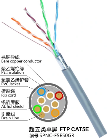
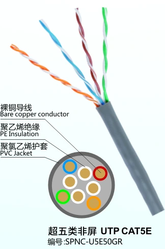
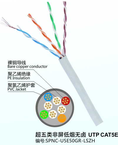
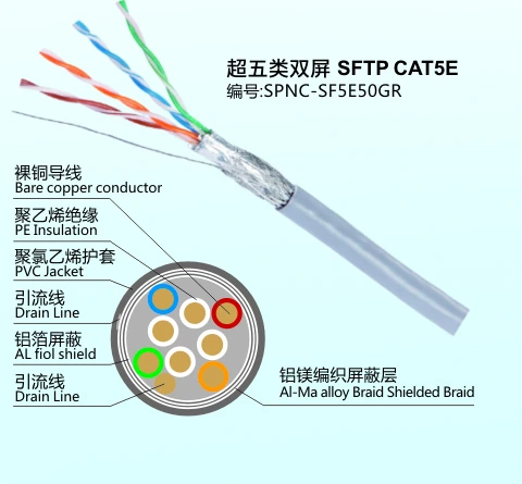
Certification measures what was installed, so the ceiling is set at the reel. Where the part number publishes them, the figures that appear in a test report come from the cable: a nominal impedance of 100 ± 15 ohm and conductor resistance no higher than 9.38 ohm per 100 m at 20 °C on the CAT5E assemblies, over a 0.50 mm bare copper conductor drawn through the CAT5E and CAT6 families.
A reel that drifts outside the impedance window shows up as return loss, not as a bad termination, and no amount of reworking will fix it. That is the one failure mode where the tester is telling you to reject material rather than redo labour.
The CAT5E to CAT7 network cable range publishes those figures part by part, and the patch cord range carries the same impedance and resistance limits as the bulk cable it is made from, so a channel built from both ends is measured on consistent terms. Where a job is a whole floor rather than a set of drops, the office LAN application page covers the rest of the bill of materials.
What to hand over with the test results
A test report is only evidence if somebody else can reproduce it. Six things belong in the handover pack:
- Tester model, serial number and calibration date, with the accuracy level the instrument is qualified to.
- The configuration used — permanent link, channel or MPTL — and which adapters were fitted.
- The limit set name and the standard edition the contract named.
- Every result, including the failures. A report containing only passes cannot show that a fault was found and corrected.
- As-built length per link and the outlet labelling scheme, so a later fault can be located without a full survey.
- For screened jobs, where the screen was earthed and how continuity was verified.
If the client's own patch cords form part of the acceptance, run a channel test as a separate exercise with those cords fitted. That splits a cable problem from a cord problem in one visit instead of two, and it gives the customer a document that covers the parts they own.
Frequently asked
Should a new installation be certified as permanent link or channel?
Permanent link is the normal answer for a new installation: it measures the horizontal cable and the terminations the contractor installed and warrants, and it is the configuration most manufacturer warranties name. Use channel when the acceptance includes the customer's own patch cords, or when the problem being chased is end-to-end application performance.
Can a channel pass while the permanent link fails?
Yes. Channel limits carry headroom for the patch cords, so a pair of compliant cords can cover a marginal permanent link. That is why a channel report is weak evidence of installation quality, even when every result on it is green.
Which limit set should I select for a CAT6A job?
The one the contract names. Set the tester to CAT6A limits, confirm the adapters are CAT6A rated, and check that jacks, panel and cords are the same category. Testing CAT6A cable with a CAT6 limit set produces a pass that certifies nothing.
Why does the tester report a length longer than the route?
Length is calculated from the cable's nominal velocity of propagation, so an NVP that does not match the reel shows the wrong length. Set NVP from the cable datasheet first, then compare the result with the measurement of the as-built route.
Do you supply cable and cords for projects that will be certified?
Yes. Bulk cable and patch cords are produced and tested on the same lines, and the published impedance and conductor resistance limits apply to both. Ask for the datasheet and test documentation for the part numbers on your schedule.
Need the actual part numbers?
The product pages carry the full specification for every item.